Exploring possibilities of controlling servos of robot armn connected to Arduino Uno
Using ESP8266 as wifi interface for Arduino Uno
I have used ESP8266 for many tasks in the Fab Academy, so it was quite obvious that I started to explore from that hardware perspective also in this task.
Because Arduino Uno doesn't have wifi-connectivitiy like ESP8266 and ESP32, it needs separate riser card or it needs to communicate with other controllers via e.g. serial connection
I found some tutorials about that. Maybe best one was done by Maker.pro pages. Their tutorial demonstrated how one can create webpage for controlling servo (in our case one of the robot arm controls). Webpage would run on ESP8266 (ESP would be actually www-server) and communicate with arduino through serial connectivity. See more: https://maker.pro/arduino/tutorial/how-to-make-a-web-controlled-servo-with-arduino-and-esp8266
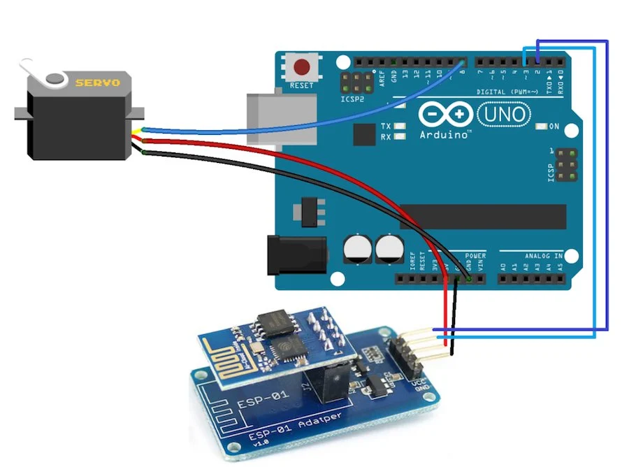
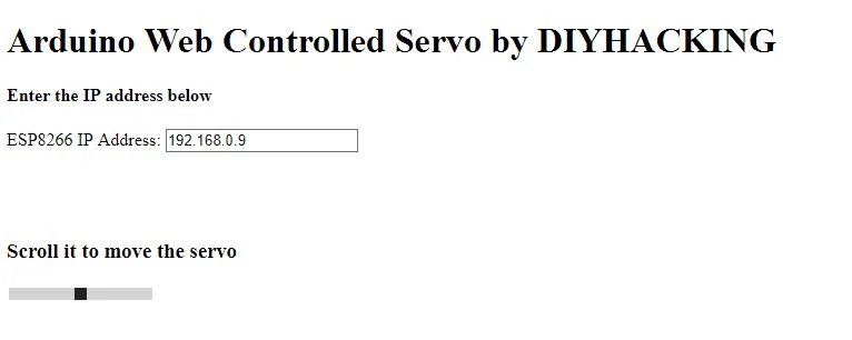
In this case ESP8266 would be connected to ground, voltage and RX/TX pins (serial connectivity). This was pretty promising approach, but I wasnt happy with the graphics on the www-pages. Reason for my disappointment was the fact that I had already used Node Red and MQTT in my ealier assigments to communicate with ESP8266
How to build controls so that I could actually use Node Red? Is ESP8266 just increasing the complexity?
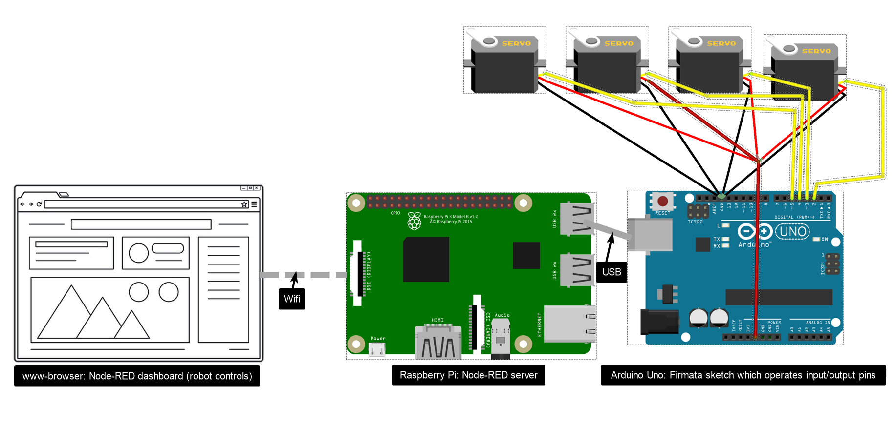
I would like to control robot arm via web browser, but not so that underpowered ESP8266 would be the wwww-server. Instead, I wanted to build system where Raspberry Pi would run Node Red server and I would be able to use scalable and good looking pages for controlling the robot.
So, in practise, I decided to remove ESP8266 from the equation and instead decided to explore how to hookup Rapsberry Pi and Arduino Uno together and how to use Node Red in this combination for creating modern controls for our project.
Node-Red: Interacting with Arduino -pages (key to solution!)
I did remember from my earlier Node-RED experimentations that it had support to Raspberry Pi's local GPIO pins. That I could use those I/O connectors directly fromn the Node-RED unser interface. So when I decided to skip of using ESP8266, I had intuition that I could atleast use Raspberry Pi pins for serial communication between Arduino Uno and Raspberry Pi.
However, I couldnt imagine at all, that even something better was available, before I found the documentation page below:
There are several ways to interact with an Arduino using Node-RED. They all assume the Arduino is connected to the host computer via a USB serial connection.
THis documentation was very important step for me to understand how to control arduino through Node-RED.
Connection Method A: Arduino ethernet or wifi extension (hat)
This would be most viable method in normal conditions (read: outside of the fab academy). However, this would be too easy ;-)
See more: https://www.arduino.cc/en/Guide/ArduinoWiFiShield
Decision: Not to be used
Connection Method B: Serial Connection
Arduino Uno has dedicated tx (transmit) and rx (receive) pins for serial communication. This approach would have been possible for adding wireless communication e.g. with the combination of Arduino Uno and ESP8266. I saw it both complex, but also boring (so common and extremely well documented) aproach. Complexity was related to need for programming of two different board within limited timeframe.
See more: https://www.arduino.cc/en/pmwiki.php?n=Reference/serial
Decision: Not to be used
Connection Method C: Firmata
When I explored how to hook-up Arduino and Raspberry Pi together, I found Firmata! Wow! Firmata is the protocol for communicating with microcontrollers from software on a host computer. In practise, it would help a lot of using Arduino together with Raspberry Pi (Node-RED).
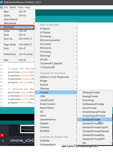
There are two main models of usage of Firmata. In one model, the author of the Arduino sketch uses the various methods provided by the Firmata library to selectively send and receive data between the Arduino device and the software running on the host computer. For example, a user can send analog data to the host using Firmata.sendAnalog(analogPin, analogRead(analogPin)) or send data packed in a string using Firmata.sendString(stringToSend). See File -> Examples -> Firmata -> AnalogFirmata & EchoString respectively for examples. Browse the API documentation here. The second and more common model is to load a general purpose sketch called StandardFirmata (or one of the variants such as StandardFirmataPlus or StandardFirmataEthernet depending on your needs) on the Arduino board and then use the host computer exclusively to interact with the Arduino board. StandardFirmata is located in the Arduino IDE in File -> Examples -> Firmata.
See more:
- https://www.instructables.com/id/Arduino-Installing-Standard-Firmata/
Decision: This will be used! Definetely!
* Windows Remote Arduino Experience * Node-Red (ra)Connection Method C: Johny-Five
Johny-Five is The Javascript Robotics and IoT platform. It communicates with Arduino using the Firmata protocol and will add new functionalities to basic implementation of Firmata, e.g. support for I2C bus.
Decision: Interesting platform, but will be used only if I have a need for a) javascript programming or b) extended cabapilities on to top of basic firmata
Installing and testing Firmata
First you need to prepare Arduino to support Firmata protocol
I did start of using firmata by loadfing a general purpose sketch called StandardFirmata on the Arduino board and then used my laptop to interact with the Arduino board. StandardFirmata is located in the Arduino IDE in File -> Examples -> Firmata.
Before compiling and uploading the sketch, I did check that board is Arduino Uno and that com port is correct one
Next step is to test Firmata protocol
When Arduino Uno is programmed to use firmata protocol, you can test that it really works. It is very straigforward, because there are available programs for that purpose.
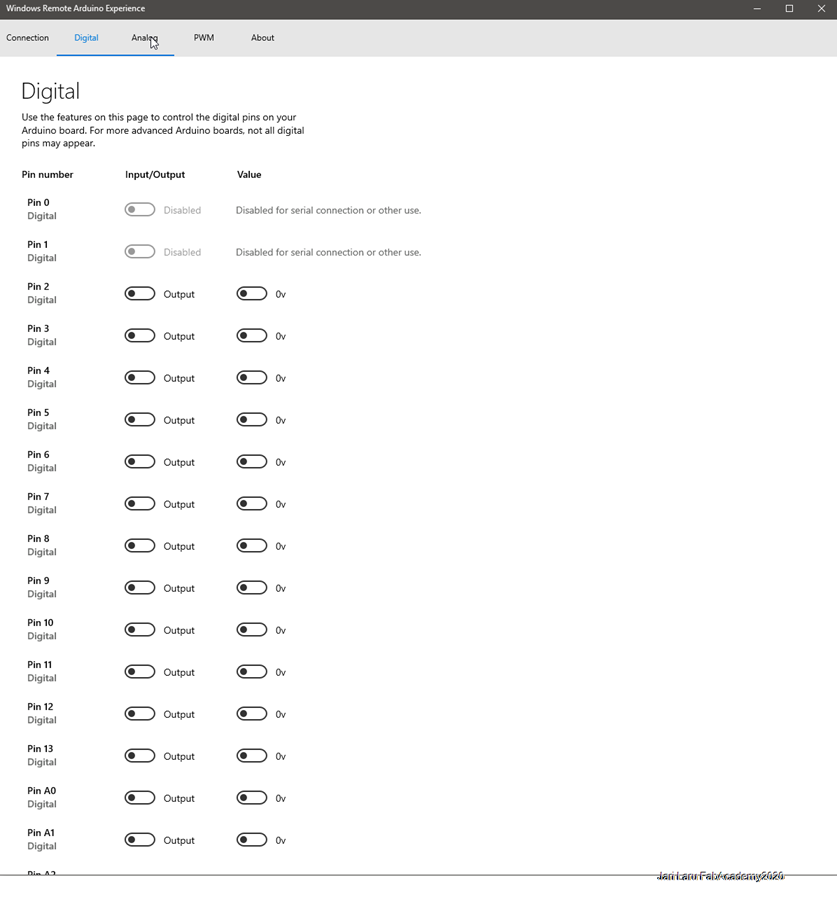
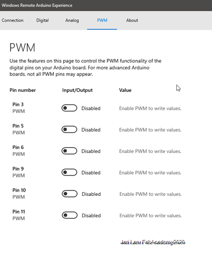
I did install "Windows Remote Arduino Experience" which gave me control to all digital, analow and PWM outputs, but also possilibility to read states to sensors connected to Arduino.
Download here software for Windows 10: https://www.microsoft.com/en-us/p/windows-remote-arduino-experience/
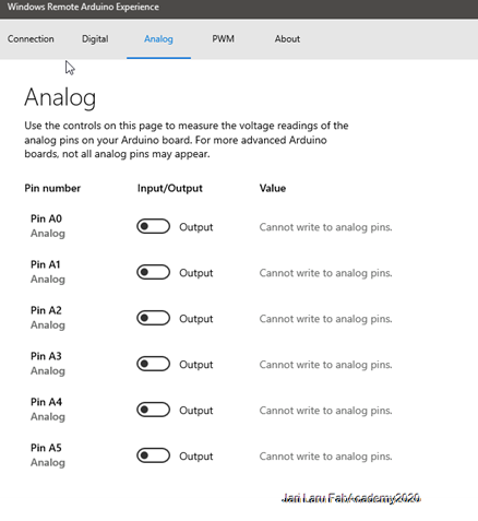
Actual testing was done as it follows:
- Check that digital pin 13 is in the output mode
- Turn it on by flipping the switch
- Check that onboard led (pin13) is lit
- If it's lit and it follows the position of the switch, firmata is working properly
Configuring Node-RED dashboard and nodes
I actually found firmata while exploring how to control Arduino by using Node-RED. Node-RED was familiar for me from the earlier assigments (where I used it with MQTT networking protocol). Node-RED is very sophisticated way to create user-interfaces for prototyping and tinkering projects.
So, in the context of our group work assigment I did create controls for four servo motors and integrated those into Arduino with help of Firmata and Node-RED. In this phase I changed from Windows 10 operating system into Raspberry Pi running with Rasbpian.
I have installed in the earlier assigments necessary packages for Node-RED and practised how to use it, so I don't explain those basics again here. Instead go there: week15. Networking and communications.html
See more:- Node-RED: https://nodered.org/
- Firmata in the context of Node-RED: https://nodered.org/docs/faq/interacting-with-arduino
In practise, hardware configuration did look like this:
Installing Firmata into Node-RED
Change directory to your Node-RED user directory, this is normally ~/.node-red
cd ~/.node-redThen install the Arduino nodes (input and output nodes to Node-RED)
npm install node-red-node-arduinoFinally restart Node-RED by using command: node-red-restart from Linux console (Raspberry Pi) , and reload the editor in the browser (the machine in same network or the same Raspberry Pi machine). There should now be two new Arduino nodes in the palette
Configuring the nodes and creating the Flows
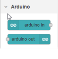
Test with simple node flowFirst I did create simple test flow where switch did lit LED on output 13 (default Arduino test led physically on PCB). Test succeedeed so I did proceed further
Final flows between dashboard and arduino nodesNext I dragged four output nodes (arduino node) into flow canvas and also four darhboard sliders into same canvas. Dashboard is the userinterface which is visible for end-user
I did connections between one slider node to one arduino output node and at the same time made basic configurations for alle nodes (e.g. choose from dropdown in arduino output node that it's servo and gave names to nodes)
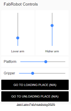
Configuring the layout (user interface)Next I opened dashboard dialog from the right side of the view where I did create Tab for "FabRobot Controls". Then I went back to nodes and double clicked each node and then added node by node them to be a part of FabRobot Controls Layout.
Although layout is automatically organized, I wanted to change two sliders into vertical position. It was done e.g. in the context of lower arm -node, just double clicking and then choosing "size". In this dialog it's easy to spesify the orientation of the slider.
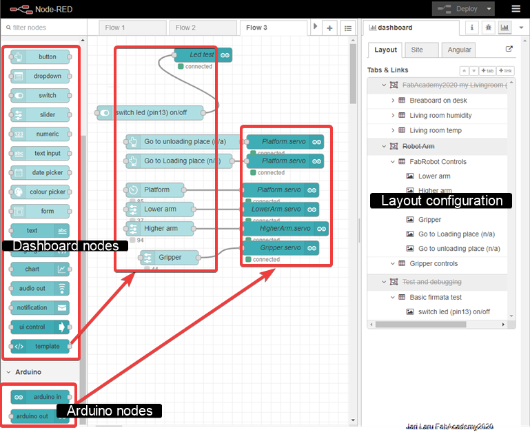
User interface has also two buttons for commands to bring robot back to loading place or sendit it to unloading place. Those are not yet integrated into servos and are like "future work"
Testing the configuration with the actual robot
We didn't have time to test these controls with the actual robot, but user interface is tested with servos anyway. Later on also video about the controlling the real robot will be presented.
Below is screenshot of user interface, which is scalable, ie. it can be used with mobile phone, tablet, laptop, desktop etc.